PRODUCTS & SERVICES
impact modal test of
a wind turbine blade
A project on a wind turbine blade shows how to
improve impact testing of weakly damped structures
AEROSPACETESTINGINTERNATIONAL.COM // SEPTEMBER 2019 105
Wind turbine blades are one of the core
components of a wind turbine
generator. The cost of the blades
accounts for 15% to 20% of total expense.
Blade design directly influences the
efficiency, productivity and economic benefit
of a wind turbine generator. Wind turbine
blades usually take a thin shell shape and are
typically produced from glass fiber reinforced
plastic. The main beam of the blade and its tip
are typically reinforced with carbon fiber
whilst the leading and trailing edge are made
of interlayer structure composite material.
Data shows that wind energy availability
increases by 12% as the diameter of blades
increases by 6%. Nowadays the diameter of
blades of a 2MW wind turbine generator can
reach 80m, making the manufacturing,
delivery and installation of wind turbines
more difficult than in the past.
Usually, the nominal rotating speed of
doubly fed induction generator is 30rpm
(0.5Hz). As the diameter of the blades
increases, their resonance frequencies or
modal frequencies decrease. When the
resonance frequencies approach the rotating
speed, higher vibration levels occur and the
wind turbine generator is subjected to higher
alternating stress. Thus, the trailing edge of
the blade will crack more easily and the
service life will be shorter than the design
value. So, it is important to consider the
resonance frequencies already in the design
phase of the wind turbine. Although the wind
turbine design software takes the risk of
blade resonance excited by rotating speed
into consideration, a modal test is required to
account for structural deviations from
manufacturing and installation.
In December 2018, a team from m+p
international was invited by a wind turbine
company to do an impact test of a 60m-long
wind turbine blade. The root part of the blade
was installed horizontally onto a test bed
through bolts, adjusting the direction in a
lowest resonance frequency of the blade
under test.
The roaming hammer, fixed transducer
method was used to run the test. Because the
resonance frequencies of the structure were
low, and the damping ratio relatively small,
the duration to acquire a data block was set
to 64 seconds to measure the complete
vibration response of the blade and to gain a
frequency resolution of 0.016Hz. For the
impact excitation 32 different locations
distributed evenly along the leading and
trailing edge were used. The structure was
excited by an impact hammer at each point in
the vertical and horizontal direction.
After modal parameter identification, the
team obtained the parameters of the first four
modes as shown in table 1.
Obviously, the turbine blade is a weakly
damped structure. The team from m+p
international improved the widely used poly
reference time domain method (PTD) to PTD
plus to extract the modal parameters of such
kind of weakly damped structures. PTD plus
can obtain clean stabilization charts directly
and effectively improve the quality of the
results of the modal identification process
even for unexperienced users.\\
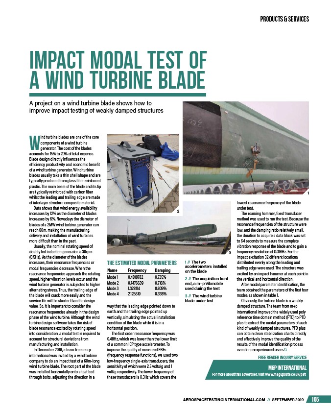
1 // The two
accelerometers installed
on the blade
2 // The acquisition frontend,
a m+p Vibmobile
used during the test
3 // The wind turbine
blade under test
FREE READER INQUIRY SERVICE
m&P International
For more about this advertiser, visit www.magupdate.co.uk/pati
the estimated modal parameters
Name Frequency Damping
Mode 1 0.4819782 0.735%
Mode 2 0.7476639 0.716%
Mode 3 1.328114 0.609%
Mode 4 2.126619 0.338%
1
3
2
way that the leading edge pointed down to
earth and the trailing edge pointed up
vertically, simulating the actual installation
condition of the blade while it is in a
horizontal position.
The first order resonance frequency was
0.48Hz, which was lower than the lower limit
of a common ICP type accelerometer. To
improve the quality of measured FRFs
(frequency response functions), we used two
low-frequency single-axis transducers, the
sensitivity of which were 2.5 volts/g and 1
volt/g respectively. The lower frequency of
these transducers is 0.3Hz which covers the
/AEROSPACETESTINGINTERNATIONAL.COM
/pati