from oil wells to gas wells and everything
in the boundary zone); research into fl ow
measurement and fl ow regimes; and
understanding fl ow structures using novel
research techniques. The facility is also built
for technology development; supporting
SMEs; largest multiphase fl ow rates in the
world for the combination of gas, oil, and
water; and impartial, and independent
laboratory certifi ed ISO17025.
The services are aimed at a range of
audiences, including:
● Oil and gas companies who are endusers
of fl ow metering equipment and who
require accurate measurement;
● Governments who wish to ensure that
taxes are paid correctly and fairly;
● Multiphase solution developers needing
validation/performance certifi cation;
● Universities developing software and who
require fl ow modelling understanding;
● And engineering, procurement and
construction fi rms that build entire
structures, and wish to select appropriate
equipment and ensure it meets
specifi cations.
TO THE FUTURE
Two joint industry projects (JIP) and one
joint research project (JRP) have already
been initiated and will take place in the
AMF. Current projects include:
● JIP: Oil & Gas Industry Verifi cation
of Flow Meters and The Use of Such
OIL & GAS – R&D
Equipment – the fi nancial exposures for
oil/gas fi rms means that they have to
ensure, validate, and rank products on
the market. The right meter needs to be
selected from day one.
● JIP: Water Cut Meter Performance
– this is a recurring issue in oil and gas
companies, with roughly 3.5 times more
water than oil produced. There is a cost
associated process and dispose of the
water.
● JRP: Flow Mapping, Flow Structure,
and Flow Regimes – as the oil and gas
industry moves towards digital solutions,
this requires a greater understanding of
fl uid mechanics and fl ow structures and
how to model them.
“There will also be opportunities
for universities to access the facility
through collaborative work, which can
help to improve understanding of fl uid
mechanics, and modelling and software
development,” concludes Pieper.
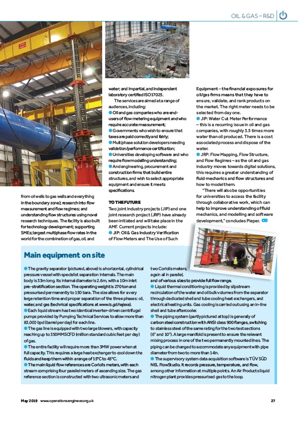
Main equipment on site
● The gravity separator (pictured, above) is a horizontal, cylindrical
pressure vessel with specialist separation internals. The main
body is 33m long. Its internal diameter is 2.6m, with a 10m inlet
pre-stratifi cation section. The operating weight is 270 ton and
pressurised permanently to 150 bara. The size allows for a very
large retention time and proper separation of the three phases: oil,
water, and gas (technical specifi cations at www.is.gd/najexa).
● Each liquid stream has two identical inverter-driven centrifugal
pumps provided by Pumping Technical Services to allow more than
83,000 bpd (barrel per day) for each line.
● The gas line is equipped with two large blowers, with capacity
reaching up to 350MMSCFD (million standard cubic feet per day)
of gas.
● The entire facility will require more than 3MW power when at
full capacity. This requires a large heat exchanger to cool down the
fl uids and keep them within a range of 15°C to 45°C.
● The main liquid fl ow references are Coriolis meters, with each
stream comprising four parallel meters of ascending size. The gas
reference section is constructed with two ultrasonic meters and
two Coriolis meters,
again all in parallel,
and of various sizes to provide full fl ow range.
● Liquid thermal conditioning is provided by slipstream
recirculation of the water and oil bulk volumes from the separator
through dedicated shell and tube cooling heat exchangers, and
electrical heating units. Gas cooling is carried out using an in-line
shell and tube aftercooler.
● The piping system (partly pictured at top) is generally of
carbon steel construction with ANSI class 900 fl anges, switching
to stainless steel of the same rating for the two test sections
(6” and 10”). A large manifold is present to ensure the relevant
mixing process in one of the two permanently mounted lines. The
piping can be changed to accommodate any equipment with pipe
diameter from two to more than 14in.
● The supervisory system data acquisition software is TÜV SÜD
NEL FlowStudio. It records pressure, temperature, and fl ow,
among other information at multiple points. An Air Products liquid
nitrogen plant provides pressurised gas to the loop.
May 2019 www.operationsengineer.org.uk 27
/najexa)
/www.operationsengineer.org.uk