Antenna
integration
What are the differences between SMD antennas with fl exible, PFC antennas and how do
you integrate them into a design? Geoff Schulteis considers some options
So why does the SMD require a
ground plane? Other forms of dipole
antennas use two radiators which
work together, where the length
of each radiator is related to the
wavelength of the frequency. SMD
antennas have only one radiator, so in
their case, the host PCB, which is also
a conductive surface, becomes the
second radiator through reciprocity.
This means that the ground plane
length is important. It must relate to
the lowest wavelength, but if it is too
short the antenna will lose ef ciency.
SMD antennas are designed to
be used in different positions on the
PCB, and each has its own individual
ground plane requirements. For
example, some are designed to be
placed on an edge of a PCB, and
some are designed for a corner. A PCB
designer should choose the antenna
that suits the design best, and also
allow for the ground plane, which will
be speci ed in the manufacturer’s
datasheet.
FPCs do not require a ground plane
to radiate, which means they allow the
designer more freedom to arrange the
components in the circuit within the
design.
Connection to other components
Both SMD and FPC antennas need to
be designed-in with care. The FPC is
different to the chip antenna in that
the coax cable actually becomes an
active part of the antenna when it is
working. This means that the routing
of the cable is very sensitive, and
there is a risk that the antenna could
pick up noise from other components
close by. We advise routing the cable
with care, to avoid interference from
any other component.
A DC blocking capacitor should be
placed in line to protect the RF front
end.
The same integration rules apply
for SMD and FPC antennas. All
transmission lines should be designed
to have a characteristic impedance
Embedded antennas, also known
as chip antennas, or SMD (surface
mount design) antennas, are used
in on-board devices, small trackers,
remote monitoring, Femto/PICO base
stations, point of sale terminals, and
smart meters. They are popular due to
their compact size, which makes them
suitable for small devices. However,
as connected devices become smaller
and continue to shrink, designers
need to squeeze their chosen antenna
solution into even smaller PCBs.
SMD antennas may be the obvious
choice for a small PCB, but there is
an alternative. Flexible printed circuit
(FPC) antennas can be a better t in
certain designs. FPC antennas are
widely used in applications where
there is insuf cient space for a SMD
antenna.
Device and antenna position
As devices shrink and space for the
components becomes more limited,
the board layout requires more care.
SMD antennas offer the advantage
of tting into small spaces on the PCB.
Flexible antennas are used differently.
They are extremely slim, typically just
0.15mm thick, which means they can
be used in slim, lightweight devices, or
they can be folded and tucked into the
housing of the device.
Ground plane
With an SMD antenna, the design
needs to allow for a ground plane, but
FPCs do not require one.
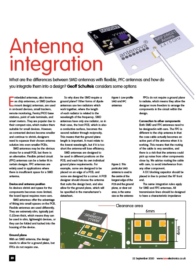
6mm
Figure 1: Low profi le
SMD and FPC
antennas
Figure 2: This
particular SMD
antenna is used in
the centre of the
longest edge of the
PCB and the ground
plane, or clear out
area, is the same
size as the antenna
Clearance area
4mm
20 22 September 2020 www.newelectronics.co.uk
/www.newelectronics.co.uk