PRODUCT PROFILE 47
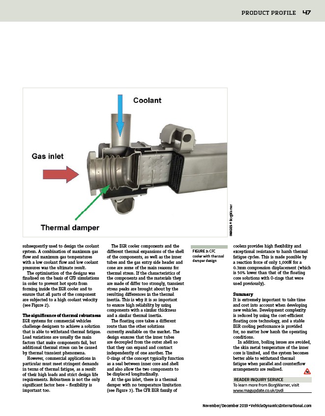
FIGURE 3: CFC
cooler with thermal
damper design
READER INQUIRY SERVICE
To learn more from BorgWarner, visit
www.magupdate.co.uk/pvdi
November/December 2019 • VehicleDynamicsInternational.com
subsequently used to design the coolant
system. A combination of maximum gas
flow and maximum gas temperatures
with a low coolant flow and low coolant
pressures was the ultimate result.
The optimisation of the designs was
finalised on the basis of CFD simulations
in order to prevent hot spots from
forming inside the EGR cooler and to
ensure that all parts of the component
are subjected to a high coolant velocity
(see Figure 2).
The significance of thermal robustness
EGR systems for commercial vehicles
challenge designers to achieve a solution
that is able to withstand thermal fatigue.
Load variations are usually the main
factors that make components fail, but
additional thermal stress can be caused
by thermal transient phenomena.
However, commercial applications in
particular must meet stringent demands
in terms of thermal fatigue, as a result
of their high loads and strict design life
requirements. Robustness is not the only
significant factor here – flexibility is
important too.
The EGR cooler components and the
different thermal expansions of the shell
of the components, as well as the inner
tubes and the gas entry side header and
cone are some of the main reasons for
thermal stress. If the characteristics of
the components and the materials they
are made of differ too strongly, transient
stress peaks are brought about by the
resulting differences in the thermal
inertia. This is why it is so important
to ensure high reliability by using
components with a similar thickness
and a similar thermal inertia.
The floating core takes a different
route than the other solutions
currently available on the market. The
design ensures that the inner tubes
are decoupled from the outer shell so
that they can expand and contract
independently of one another. The
O-rings of the concept typically function
as a seal between inner core and shell
and also allow the two components to
be displaced longitudinally.
At the gas inlet, there is a thermal
damper with no temperature limitation
(see Figure 3). The CFR EGR family of
coolers provides high flexibility and
exceptional resistance to harsh thermal
fatigue cycles. This is made possible by
a reaction force of only 1,000N for a
0.3mm compression displacement (which
is 50% lower than that of the floating
core solutions with O-rings that were
used previously).
Summary
It is extremely important to take time
and cost into account when developing
new vehicles. Development complexity
is reduced by using the cost-efficient
floating core technology, and a stable
EGR cooling performance is provided
for, no matter how harsh the operating
conditions.
In addition, boiling issues are avoided,
the skin metal temperature of the inner
core is limited, and the system becomes
better able to withstand thermal
fatigue when parallel and counterflow
arrangements are realised.
IMAGES: © BorgWarner
/pvdi
/VehicleDynamicsInternational.com