78
PRODUCTS & SERVICES
SIGNAL CONDITIONING FOR
ROCKET ENGINE TESTING
NASA’s John C. Stennis Space Center has tested
rocket engines for more than 40 years from the
Saturn-V program in the 1960s to current testing of
engines for the Space Launch System
Testing of rocket engines requires
hundreds of sensors to measure critical
parameters such as thrust, fuel flow,
pressure, vibration, strain, and temperature at
extreme conditions. Thousands of feet of
cable are routed through the test stand to the
engine, portions of which are subjected to the
harsh daily outdoor environment.
A signal conditioning strategy is required
for each sensor type to minimize unwanted
noise and maximizes data quality. The
hardware must be flexible and universal and
not require a separate card type or mode card
plug-on for each transducer type, to minimize
spare requirements and simplify operation
and programming. Precision’s 28000 rocket
engine test suite of signal conditioning
products installed at NASA Stennis provides a
solution for both static and dynamic sensors.
High accuracy excitation and DC gain is
provided for reduced uncertainty and
JUNE \\ AEROSPACETESTINGINTERNATIONAL.COM
the most quiet state so that no noise coupling
occurs to properly functioning channels.
Precision’s products feature fully
automated built-in calibration routines for
excitation, amplifier gain, offset and commonmode
rejection that is run on the unit in place
at any time allowing you to optimize system
performance at any operating ambient. In
addition, the system provides in-situ test
methodology for end-to-end system
calibration that is NIST traceable. \\
FREE READER INQUIRY SERVICE
PRECISION FILTERS
1 // The Precision 28000
Signal Conditioner for
Rocket Engine Testing
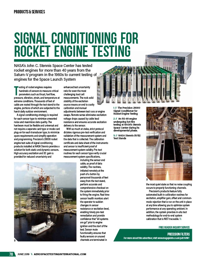
2 // An RS-68 engine
undergoing hot-fire
testing at NASA’s Stennis
Space Center during its
developmental phase.
3 // NASA Stennis B1/B2
Test Stands
For more about this advertiser, visit www.magupdate.co.uk/pati NOW!
enhanced test uncertainty
ratio for even the most
challenging load cell
measurements. The rock solid
stability of the excitation
source means an end to costly
calibration and manual
adjustments between test runs or engine
swaps. Remote sense eliminates excitation
voltage drops caused by cable lead
resistance and ensures accurate excitation
delivery to the sensor.
With so much at stake, strict protocol
dictates rigorous pre-test verification and
validation of the measurement system and
the data that is collected. The calibration
certificate and data sheet of the instruments
and sensor is insufficient proof of
measurement system validity. Pre-test
routines for each sensor type verify crucial
measurement system specifications,
including the sensor and
cable, as proof of data
validity. The routines,
initiated remotely at the
push of a button by
personnel thousands of feet
away from the test stand,
perform accurate and
comprehensive checkout on
the system immediately prior
to firing the engine. Real time
sensor health monitors alert
the operator to sudden
changes in sensor
resistance or excitation level,
enabling timely pre-test
remediation and provide
confidence that “all systems
are go” prior to engine
ignition and the start of the
test. Sensor mute
functionality ensures that
faulty sensors or unused
3 channels are terminated in
2
/AEROSPACETESTINGINTERNATIONAL.COM
/pati