PRODUCTS & SERVICES
IMPROVED RESONANCE TESTING
Vibration testing accuracy for
products such as turbine blades can
be increased with the use of the latest
software analysis techniques
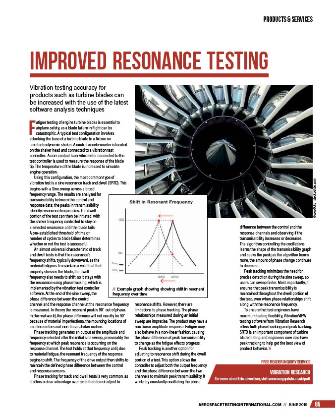
// Example graph showing showing shift in resonant
frequency over time
AEROSPACETESTINGINTERNATIONAL.COM // JUNE 85
Fatigue testing of engine turbine blades is essential to
airplane safety, as a blade failure in flight can be
catastrophic. A typical test configuration involves
attaching the base of a turbine blade to a fixture on
an electrodynamic shaker. A control accelerometer is located
on the shaker head and connected to a vibration test
controller. A non-contact laser vibrometer connected to the
test controller is used to measure the response of the blade
tip. The temperature of the blade is increased to simulate
engine operation.
Using this configuration, the most common type of
vibration test is a sine resonance track and dwell (SRTD). This
begins with a Sine sweep across a broad
frequency range. The results are analyzed for
transmissibility between the control and
response data; the peaks in transmissibility
identify resonance frequencies. The dwell
portion of the test can then be initiated, with
the shaker frequency controlled to stay on
a selected resonance until the blade fails.
A pre-established threshold of time or
number of cycles to blade failure determines
whether or not the test is successful.
An almost universal characteristic of track
and dwell tests is that the resonance’s
frequency shifts, typically downward, as the
material fatigues. To maintain a valid test that
properly stresses the blade, the dwell
frequency also needs to shift, so it stays with
the resonance using phase tracking, which is
implemented by the vibration test controller
software. At the end of the sine sweep, the
phase difference between the control
channel and the response channel at the resonance frequency
is measured. In theory the resonant peak is 90° out of phase.
In the real world, the phase difference will not exactly be 90°
because of material imperfections, the mounting locations of
accelerometers and non-linear shaker motion.
Phase tracking generates an output at the amplitude and
frequency selected after the initial sine sweep, presumably the
frequency at which peak resonance is occurring on the
response channel. The test holds at that frequency until, due
to material fatigue, the resonant frequency of the response
begins to shift. The frequency of the drive output then shifts to
maintain the defined phase difference between the control
and response sensors.
Phase tracking for track and dwell tests is very common, as
it offers a clear advantage over tests that do not adjust to
difference between the control and the
response channels and observing if the
transmissibility increases or decreases.
The algorithm controlling the oscillations
learns the shape of the transmissibility graph
and seeks the peak; as the algorithm learns
more, the amount of phase change continues
to decrease.
Peak tracking minimizes the need for
precise detection during the sine sweep, so
users can sweep faster. Most importantly, it
ensures that peak transmissibility is
maintained throughout the dwell portion of
the test, even when phase relationships shift
along with the resonance frequency.
To ensure that test engineers have
maximum testing flexibility, VibrationVIEW
testing software from Vibration Research
offers both phase tracking and peak tracking.
SRTD is an important component of turbine
blade testing and engineers now also have
peak tracking to help get the best view of
product behavior. \\
FREE READER INQUIRY SERVICE
vibration research
For more about this advertiser, visit www.magupdate.co.uk/pati
resonance shifts. However, there are
limitations to phase tracking. The phase
relationships measured during an initial
sweep are imprecise. The product may have a
non-linear amplitude response. Fatigue may
also behave in a non-linear fashion, causing
the phase difference at peak transmissibility
to change as the fatigue effects progress.
Peak tracking is another option for
adjusting to resonance shift during the dwell
portion of a test. This option allows the
controller to adjust both the output frequency
and the phase difference between the two
channels to maintain peak transmissibility. It
works by constantly oscillating the phase
© JavaDuke - stock.adobe.com
/AEROSPACETESTINGINTERNATIONAL.COM
/pati
/stock.adobe.com