videoscopes
2 3
the selection in the 3D view. This method
helps the user to visually confirm that the
selected pixel is truly where it should be in
3D space, thus reducing the risk of
misplaced measurement points, avoiding
the need to re-measure and increasing
inspection efficiency. To understand the
internal shapes and features of inspected
components even better, it is sometimes
possible to carry out virtual slicing of 3D
models. With this function, users can
easily remove sections from the model to
get the best possible view.
CASE STUDY: TIP GAP CLEARANCE
A good example of a challenging
environment that requires accurate
measurement and the ability to confirm
reference points is when conducting a tip
gap clearance measurement. This type of
measurement looks at the distance
between the tip of a blade (for example in
the high-pressure compressor) and the
shroud of the engine.
In gas turbines, the size of the clearance
between the tip of the blades and the
shroud is essential for its operation. If
there is no adequate gap, this can lead to
damage of the blades; if the gap is too large,
gas passes through the clearance, which
leads to pressure loss and reduced engine
efficiency. For these reasons, the tip gap
clearance must remain within specification
126 SHOWCASE 2020 \\ AEROSPACETESTINGINTERNATIONAL.COM
throughout the service life of the engine.
Videoscopes with advanced measurement
and 3D modeling capabilities are well
suited to inspect whether wear or
deformation have altered the gap size.
Enlarging the area of inspection means
moving further away from the target
object within the depth of field of the lens.
To carry out measurements, however, the
furthest distance away from the target for
a conventional scope is often around 20
mm. Beyond this distance, the accuracy
drops and in some cases, measurement is
not possible at all.
When measuring any critical part using
a videoscope, key factors affecting
measurement accuracy are the size of the
object to be measured and the distance
from the object. It is important to know
how far away the scope tip is from the
object before starting the
measurement.
Addressing this issue,
modern videoscopes can
determine tip-to-target
distance (or ‘Z’ distance) on
the live image before
measurement starts. By
measuring the Z distances
of all pixels within the
stereo image, samples of
these distances can be presented in realtime
to the user, highlighting as much as
five individual Z values at any region of
the stereo image. This assists the user in
developing an understanding of the
surface profile and provides key
information needed for confident
measurements.
This feature greatly assists tip gap
clearance measurements, where a
straightforward distance measurement is
unlikely to be accurate, due to the angle
between the videoscope and the tip gap. For
this reason, tip gap clearance measurement
is taken as a depth or height gap
measurement, where a reference plane is
set at a known surface and measurements
are taken perpendicular to this plane.
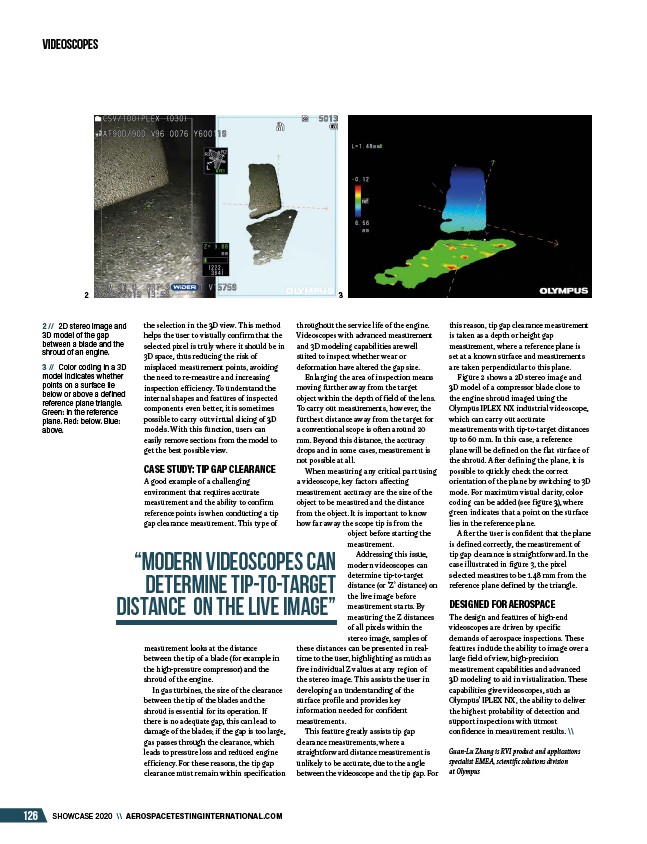
Figure 2 shows a 2D stereo image and
3D model of a compressor blade close to
the engine shroud imaged using the
Olympus IPLEX NX industrial videoscope,
which can carry out accurate
measurements with tip-to-target distances
up to 60 mm. In this case, a reference
plane will be defined on the flat surface of
the shroud. After defining the plane, it is
possible to quickly check the correct
orientation of the plane by switching to 3D
mode. For maximum visual clarity, colorcoding
can be added (see figure 3), where
green indicates that a point on the surface
lies in the reference plane.
After the user is confident that the plane
is defined correctly, the measurement of
tip gap clearance is straightforward. In the
case illustrated in figure 3, the pixel
selected measures to be 1.48 mm from the
reference plane defined by the triangle.
DESIGNED FOR AEROSPACE
The design and features of high-end
videoscopes are driven by specific
demands of aerospace inspections. These
features include the ability to image over a
large field of view, high-precision
measurement capabilities and advanced
3D modeling to aid in visualization. These
capabilities give videoscopes, such as
Olympus’ IPLEX NX, the ability to deliver
the highest probability of detection and
support inspections with utmost
confidence in measurement results. \\
Guan-Lu Zhang is RVI product and applications
specialist EMEA, scientific solutions division
at Olympus
2 // 2D stereo image and
3D model of the gap
between a blade and the
shroud of an engine.
3 // Color coding in a 3D
model indicates whether
points on a surface lie
below or above a defined
reference plane triangle.
Green: in the reference
plane. Red: below. Blue:
above.
“modern videoscopes can
determine tip-to-target
distance on the live image”
/AEROSPACETESTINGINTERNATIONAL.COM