Vibration testing
IMPROVING SINE RESONANCE
TRACK AND DWELL TESTING
An experimental comparison of tracking methods
// JOEL MINDERHOUD
It seems like sine resonance track and
dwell testing should be fairly
straightforward. Run a Sine sweep, find
a resonance frequency, then dwell on that
frequency for a pre-determined time or
until the device under test fails.
Sadly, things are not that simple in the
real world. Resonance measurement is
never fully accurate. More significantly,
resonances shift as material fatigues and,
for the test to be valid, the test frequency
also needs to shift. An engineer needs
insight into these shifts. Ideally, the
engineer should also be able to learn the
details of multiple resonances, select a
resonance for a Dwell, and then run that
test with confidence that the frequency
will stay on the resonance.
This article first examines the nature of
shifts in resonant frequencies and the
phase relationship between the control
channel and the response channel at those
frequencies. The discussion then moves to
76 SHOWCASE 2020 \\ AEROSPACETESTINGINTERNATIONAL.COM
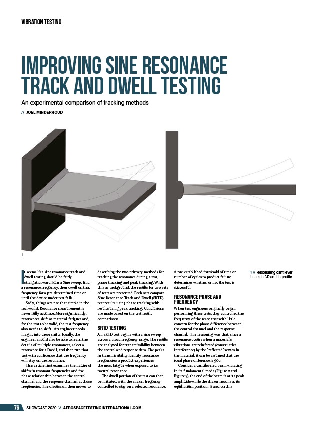
1 // Resonating cantilever
beam in 3D and in profile
1
describing the two primary methods for
tracking the resonance during a test,
phase tracking and peak tracking. With
this as background, the results for two sets
of tests are presented. Both sets compare
Sine Resonance Track and Dwell (SRTD)
test results using phase tracking with
results using peak tracking. Conclusions
are made based on the test result
comparisons.
SRTD TESTING
An SRTD test begins with a sine sweep
across a broad frequency range. The results
are analyzed for transmissibility between
the control and response data. The peaks
in transmissibility identify resonance
frequencies; a product experiences
the most fatigue when exposed to its
natural resonance.
The dwell portion of the test can then
be initiated, with the shaker frequency
controlled to stay on a selected resonance.
A pre-established threshold of time or
number of cycles to product failure
determines whether or not the test is
successful.
RESONANCE PHASE AND
FREQUENCY
When test engineers originally began
performing these tests, they controlled the
frequency of the resonance with little
concern for the phase difference between
the control channel and the response
channel. The reasoning was that, since a
resonance occurs when a material’s
vibrations are reinforced (constructive
interference) by the “reflected” waves in
the material, it can be assumed that the
ideal phase difference is 90o.
Consider a cantilevered beam vibrating
in its fundamental mode (Figure 2 and
Figure 3); the end of the beam is at its peak
amplitude while the shaker head is at its
equilibrium position. Based on this
/AEROSPACETESTINGINTERNATIONAL.COM