software testing
AEROSPACETESTINGINTERNATIONAL.COM // SHOWCASE 2020 129
1 // Better testing tools by
using standards to simplify
certification through virtual
testing and reuse of tests
2 // The structure of new
test system standard with
key modules and objects
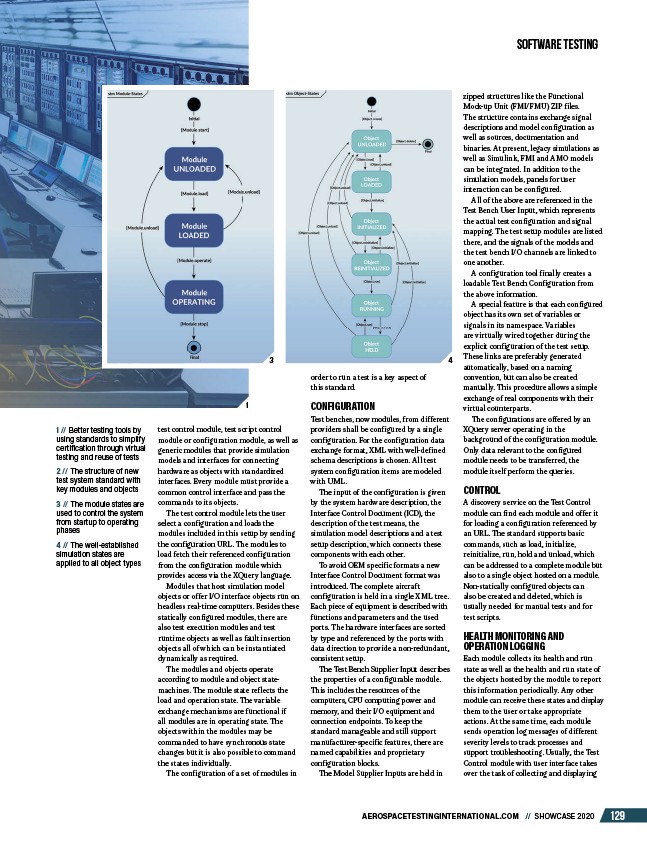
3 // The module states are
used to control the system
from startup to operating
phases
4 // The well-established
simulation states are
applied to all object types
test control module, test script control
module or configuration module, as well as
generic modules that provide simulation
models and interfaces for connecting
hardware as objects with standardized
interfaces. Every module must provide a
common control interface and pass the
commands to its objects.
The test control module lets the user
select a configuration and loads the
modules included in this setup by sending
the configuration URL. The modules to
load fetch their referenced configuration
from the configuration module which
provides access via the XQuery language.
Modules that host simulation model
objects or offer I/O interface objects run on
headless real-time computers. Besides these
statically configured modules, there are
also test execution modules and test
runtime objects as well as fault insertion
objects all of which can be instantiated
dynamically as required.
The modules and objects operate
according to module and object statemachines.
The module state reflects the
load and operation state. The variable
exchange mechanisms are functional if
all modules are in operating state. The
objects within the modules may be
commanded to have synchronous state
changes but it is also possible to command
the states individually.
The configuration of a set of modules in
order to run a test is a key aspect of
this standard.
CONFIGURATION
Test benches, now modules, from different
providers shall be configured by a single
configuration. For the configuration data
exchange format, XML with well-defined
schema descriptions is chosen. All test
system configuration items are modeled
with UML.
The input of the configuration is given
by the system hardware description, the
Interface Control Document (ICD), the
description of the test means, the
simulation model descriptions and a test
setup description, which connects these
components with each other.
To avoid OEM specific formats a new
Interface Control Document format was
introduced. The complete aircraft
configuration is held in a single XML tree.
Each piece of equipment is described with
functions and parameters and the used
ports. The hardware interfaces are sorted
by type and referenced by the ports with
data direction to provide a non-redundant,
consistent setup.
The Test Bench Supplier Input describes
the properties of a configurable module.
This includes the resources of the
computers, CPU computing power and
memory, and their I/O equipment and
connection endpoints. To keep the
standard manageable and still support
manufacturer-specific features, there are
named capabilities and proprietary
configuration blocks.
The Model Supplier Inputs are held in
zipped structures like the Functional
Mock-up Unit (FMI/FMU) ZIP files.
The structure contains exchange signal
descriptions and model configuration as
well as sources, documentation and
binaries. At present, legacy simulations as
well as Simulink, FMI and AMO models
can be integrated. In addition to the
simulation models, panels for user
interaction can be configured.
All of the above are referenced in the
Test Bench User Input, which represents
the actual test configuration and signal
mapping. The test setup modules are listed
there, and the signals of the models and
the test bench I/O channels are linked to
one another.
A configuration tool finally creates a
loadable Test Bench Configuration from
the above information.
A special feature is that each configured
object has its own set of variables or
signals in its namespace. Variables
are virtually wired together during the
explicit configuration of the test setup.
These links are preferably generated
automatically, based on a naming
convention, but can also be created
manually. This procedure allows a simple
exchange of real components with their
virtual counterparts.
The configurations are offered by an
XQuery server operating in the
background of the configuration module.
Only data relevant to the configured
module needs to be transferred, the
module itself perform the queries.
CONTROL
A discovery service on the Test Control
module can find each module and offer it
for loading a configuration referenced by
an URL. The standard supports basic
commands, such as load, initialize,
reinitialize, run, hold and unload, which
can be addressed to a complete module but
also to a single object hosted on a module.
Non-statically configured objects can
also be created and deleted, which is
usually needed for manual tests and for
test scripts.
HEALTH MONITORING AND
OPERATION LOGGING
Each module collects its health and run
state as well as the health and run state of
the objects hosted by the module to report
this information periodically. Any other
module can receive these states and display
them to the user or take appropriate
actions. At the same time, each module
sends operation log messages of different
severity levels to track processes and
support troubleshooting. Usually, the Test
Control module with user interface takes
over the task of collecting and displaying
1
3 4
/AEROSPACETESTINGINTERNATIONAL.COM