software testing
functional aircraft integration. While the
actual test software, test hardware and
related measuring instruments come from
Vector, FFT is responsible for all the
electrical and electro-mechanical systems,
construction of the control cabinets and all
the wiring and signal distribution systems.
FFT also implements the hardware
switches and controls, user operating
panels of the control stations, integration
of original airplane components and a
visualization model of the cabin ceiling for
evaluating various lighting scenarios.
CONTROL CABINETS
The largest test system is the STR (system
test rig). It includes an impressive test
bench with eight high-resolution monitors
and two original cabin touch panels. Four
PCs for the graphical user interface and
four real-time PCs on which the CANoe
test software runs work in the background.
It is noteworthy that the size and
complexity of the overall system requires a
total of four CANoe instances for
simulating and stimulating – instead of the
typical one CANoe instance. The four
instances are synchronized, which means
that each instance knows the necessary
system sizes of the other instances.
FROM COMPONENT TEST TO
REALISTIC SYSTEM TEST
Most of the equipment is housed in 15
large 19 inch control cabinets. It includes
the test and measurement hardware of the
VT System, custom interface boards,
designed and manufactured by FFT, which
establish the central junction between the
system under test and the VT System,
power supplies and original airplane
components. Due to embedded
microcontrollers and a sophisticated
switching logic, variable configurations
between aircraft components,
measurement system and simulation
hardware or an arbitrary combination,
dependent on the testing focus, can be set
by the interface boards. They are also used
to determine the exact configuration
status of the system under test including
the pin assignment of all connected
terminal devices. The STR represents an
airplane’s original configuration, including
The CIDS technology consists of two
redundant host computers, touch panels,
handsets, as well as display and indication
panels that are distributed throughout the
cabin. The extensive wiring comes together
at node points. Communication is not only
served by the numerous networks, data
buses and serial connections such as
Ethernet, ARINC 429, CAN, RS-232, RS-485
and USB, but also by analog, audio and
discrete connections. The system handles a
total of more than 6,000 signals. All
components are developed, produced,
tested and certified by Airbus Operations.
STRINGENT REQUIREMENTS
The numerous CIDS system components,
signals and communication channels have
made tests increasingly more timeintensive.
Previous test benches required
many manual interventions and operating
steps, and they did not satisfy the
preconditions for modern test automation.
So, Airbus began to search for a modern
successor system to cover growing
performance and testing requirements for
the future. The system would need to
generate all the required stimuli, monitor
all outputs and simulate the necessary
airplane environment. It would also need
to enable test engineers to create
automated test procedures easily and
rapidly. One of the most important
requirements remained that the test
system must permit easy adaptation of the
tests for different cabin configurations.
The solution that was chosen was the
one implemented in a joint project
between Vector and FFT
Produktionssysteme. It consists of a total of
three test benches at the two business sites
of Airbus Operations. Each test bench
focuses on a different aspect of testing -
component integration, system testing and
AEROSPACETESTINGINTERNATIONAL.COM // SHOWCASE 2020 93
The situation is the same for the
aerospace, maritime and automotive
industries – advances in engineering
are continually producing higher
performance and greater complexity.
Electronics and IT lead to greater comfort,
convenience, functionality, safety and
much more. But the many functions are
also increasing the number of potential
sources of error disproportionately. As a
result, managers are confronted with
demands for more efficient test strategies
and the need to automate tests as much as
possible. This article shows – based on the
example of the cabin management system
at Airbus – how standard tools and
ingenious customer-specific modifications
were used to create three large test systems
that represent the latest technology in
aircraft system testing.
Airbus Operations has business sites in
Buxtehude and Hamburg-Finkenwerder,
Germany, and is responsible for system
tests of cabin management systems for
Airbus aircrafts. The Cabin
Intercommunication Data System (CIDS) is
the electrical/electronic system’s control
center for cabin operations on all Airbus
airplanes. Its tasks include operating and
monitoring cabin lighting, the interphone
system, cabin status as well as air
conditioning and functionality of the
toilets/washrooms. It also provides
functions for passengers such as reading
lights and entertainment systems. Cabin
smoke detection and issuing alerts for
evacuations are other tasks of the CIDS.
CABIN CONFIGURATIONS
The cabin is the unique selling proposition
that distinguishes one airline from
another. This means that the cabin
function can differ significantly from
airplane to airplane, even within the same
airplane model. Each airline has different
wishes and can freely decide how many
seat rows should be installed in the
passenger area, what type of lighting, the
number of toilets and other features.
Depending on the corporate design and
branding, these differentiating properties
can range from equipment and device
layout to colors, lighting effects and even
airline-specific background music.
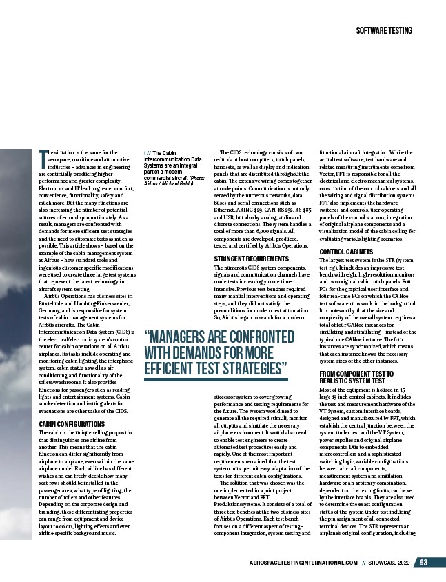
1 // The Cabin
Intercommunication Data
Systems are an integral
part of a modern
commercial aircraft (Photo:
Airbus / Michael Bahlo)
“managers are confronted
with demands for more
efficient test strategies”
/AEROSPACETESTINGINTERNATIONAL.COM