High-speed imaging
software—including the ways high-speed
imaging provides additional insights into
aerospace testing and other processes.
DAQ PICKLE SWITCH
In this first example, a pickle switch
triggers a Phantom camera via a simple
switch closure. The camera’s trigger port is
typically maintained between 4 and 5
volts. Triggering the pickle switch closes
the switch—causing the signal to drop and
triggering the camera. Pushing the button
causes the signal to drop from 5 to 0 volts,
while releasing the button returns the
signal to 5 volts. The ability to visualize the
trigger with the frame data is valuable for
researchers who need to see the trigger
position relative to the event. It is also
good practice to use this setup to ensure
the camera and DAQ system are
functioning properly.
STRAIN GAUGE
A strain gauge is composed of a material
that changes its electrical resistance based
on an applied force. In general, aerospace
engineers undergo rigorous calibration
steps prior to employing strain gauges in
an experimental system. Doing so enables
them to correlate the measured voltages
with the applied force or strain.
In this second example, a strain gauge
was attached to a tuning fork using strong,
files will automatically be saved with the
synchronized analog sensor data for future
analysis and output.
ADVANTAGES OF HIGH-SPEED
IMAGING
When used with traditional sensing
techniques and a DAQ system, high-speed
imaging adds value to the aerospace
industry in three major ways. Firstly,
incorporating the DAQ system with the
camera dramatically improves workflow
efficiency by decreasing the number of
steps necessary to synchronize the two
data streams. One team can perform the
work, rather than two or more. Secondly,
the data is all stored in a single place.
Traditionally, all data has been spread
between teams of people. Now, it is all
conveniently stored in the Cine file. Finally
and most valuably, adding visual
representation to the more abstract picture
created by sensor data can lead to new
insights. During vibration analysis of
aerospace structures, for instance,
researchers can easily see an object’s
displacement while analyzing vibration
frequencies using conventional spectral
analysis methods like Fast Fourier
Transform (FFT).
The following five case examples
illustrate some of the applications for highspeed
cameras, DAQ hardware and PCC
AEROSPACETESTINGINTERNATIONAL.COM // SHOWCASE 2020 133
WHAT IS A DATA ACQUISITION SYSTEM?
DAQ systems can measure a variety of physical, electrical
or chemical conditions by collecting, conditioning and
processing data transduced by sensors. A typical DAQ
system has the following components:
1. The DAQ measurement hardware module, which serves
as the interface between the sensors and computer.
These devices typically integrate computer bus, signal
conditioning circuits and analog-to-digital converters,
which convert incoming analog waveforms into digital
values for processing by the computer.
2. Sensors such as thermocouples, microphones,
accelerometers, strain gauges, photodiode sensors—
and more. Some sensors may require additional signal
conditioning circuitry to properly produce readable signals
for the DAQ module.
Signal conditioning often gets short shrift from users
with an imaging background. However, sensor signals
almost always need to be amplified, filtered, isolated or
otherwise manipulated prior to processing by the DAQ. In
our experience, inadequate signal conditioning is one of the
most common problems users encounter when they first
combine imaging and DAQ systems.
Users should also make sure that sensor selection and
placement, sampling rates and signal conditioning methods
are suitable for the task at hand.
3. Computer and software to control the DAQ device as well
as process, visualize and store measurement data. The realtime
link between Phantom cameras and off-the-shelf DAQ
hardware means the Phantom Camera Control software can
serve as a single tool that unifies the camera and
DAQ control.
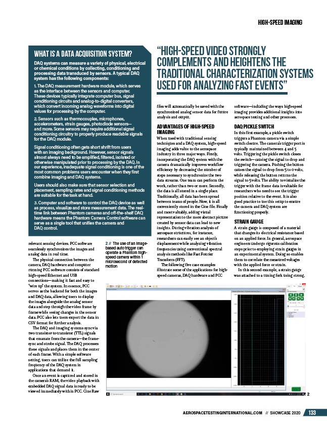
2 // The use of an imagebased
auto trigger can
operate a Phantom highspeed
camera within 1
microsecond of detected
motion
“high-speed video strongly
complements and heightens the
traditional characterization systems
used for analyzing fast events”
relevant sensing devices. PCC software
seamlessly synchronizes the images and
analog data in real time.
The physical connection between the
camera, DAQ hardware and computer
running PCC software consists of standard
high-speed Ethernet and USB
connections—making it fast and easy to
“wire up” the system. In essence, PCC
serves as the backend for both the images
and DAQ data, allowing users to display
the images alongside the analog sensor
data and step through the video frame by
frame while seeing changes in the sensor
data. PCC also lets users export the data in
CSV format for further analysis.
The DAQ and imaging systems sync via
two transistor-to-transistor (TTL) signals
that emanate from the camera—the framesync
and strobe signal. The DAQ processes
these signals and places them in the center
of each frame. With a simple software
setting, users can utilize the full sampling
frequency of the DAQ system in
applications that demand it.
Once an event is captured and stored in
the camera’s RAM, the video playback with
embedded DAQ signal data is ready to be
viewed immediately within PCC. Cine Raw
2
/AEROSPACETESTINGINTERNATIONAL.COM