PRODUCTS & SERVICES
Power play
172 // January 2020 // www.electrichybridvehicletechnology.com
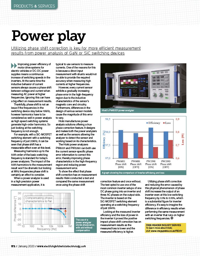
correction feature and once without.
The test opted to use one of the
most common inverter setups of one
DC phase going into an inverter and
three AC phases on the output side.
The inverter is based on the
SiC-MOSFET switching element
operating at a switching frequency
of just 20kHz.
Looking at the measured inverter
e iciency and the loss of power in
the inverter it proved the positive
impact phase shift correction has on
measurement results as the
measured loss is lower and the
measured e iciency is higher.
Utilizing phase shift correction
and reducing the error caused by
this physical phenomenon of phase
shift increases the output of an
inverter even at this low switching
frequency by 0.1% to 0.15%, which
is a substantial figure for inverter
e iciency. It’s easy to imagine the
di erence in e iciency results when
performing the same measurement
with an inverter that runs on higher
switching frequencies.
Utilizing phase shift correction is key for more efficient measurement
results from power analysis of GaN or SiC switching devices
Hioki’s PW6001 power analyzer
The use of a
power analyzer
shows phase error,
with and without
compensation
FREE READER INQUIRY SERVICE
To learn more about Hioki,
visit: www.magupdate.co.uk/PEHV
Improving power e iciency of
motor drive systems for
electric vehicles or DC-DC power
supplies means a continuous
increase of switching speeds in the
inverters. At the same time the
inductive behavior of current
sensors always causes a phase shift
between voltage and current when
measuring AC power at higher
frequencies. Ignoring this can have
a big e ect on measurement results.
Thankfully, phase shift is not an
issue if the frequencies in the
switching device stay below 10kHz,
however harmonics have to be
considered as well in power analysis
as high speed switching systems
generate high-order harmonics. So
just looking at the switching
frequency is not enough.
For example, with a SiC-MOSFET
switching element with a switching
frequency of just 20kHz, it can be
seen that phase shift has a
measurable e ect even at this level.
Measuring harmonics up to the
50th order of the basic switching
frequency is standard for today’s
power analyzers. The impact of the
50th harmonics to the measurement
result won’t be dramatic but looking
at MHz frequencies phase shift is
certainly an e ect to consider.
When a power analyzer is used
in a high precision power
measurement application, it is
typical to use sensors to measure
currents. One of the reasons for this
is because a direct input
measurement with shunts would not
be able to provide the required
accuracy when measuring high
currents at higher frequencies.
However, every current sensor
exhibits a gradually increasing
phase error in the high-frequency
region due to the inductive
characteristics of the sensor’s
magnetic core and circuitry.
Furthermore, di erences in the
design of various sensor models
cause the magnitude of this error
to vary.
Hioki manufactures power
analysis solutions o ering a true
phase correction feature. It designs
and makes both the power analyzers
as well as the sensors allowing the
analyzer to detect the sensor and
working based on its characteristics.
The Hioki power analyzers
PW6001 and PW3390 can both use
the current sensor-specific phase
error information to correct this
error, thereby improving phase
characteristics in the high-frequency
region and reducing power
measurement error.
To show the e ect that phase
shift correction has on measurement
results Hioki conducted a test and
compared the same measurement
once using the phase shift
A graph showing the comparison of inverter effi ciency and loss
/www.electrichybridvehicletechnology.com
/PEHV